20Aパイプを使う場合の注意点 / Precautions When Using 20A Pipes
(今回は計算系のTipsですので、結論だけ知りたい方はこのブログの最後に飛んでください)
管やホースで粉体を送る際の要素は、流速と流量です.ニードルバルブで生まれる圧力差が流速を決め、流速が粉を運び、流量が送れる粉の量を決め、レギュレーターで調整された圧力がそれらを維持するためのエネルギーです.
特別なランスパイプを使用する場合などにサイズが20Aしかない場合もあるでしょう.15Aから20Aに変えるには、おそらくレギュレーターの二次側圧力と流量を少し高めにする調整とと、フラックスの切出し量を少し下げる調整が必要です.湯はねのリスクは上がる可能性がありますので、蓋やシールドなどの湯はね対策の工夫はなさってください
一般的に当社のフラックス、この粉体がガスの中で沈降せずに浮遊して運ばれる限界速度は 10 m/s 前後 とされています。当社圧力調整器の2次側圧力が0.4MPaで、フィーダーの流量計で44L/min(実流量換算で20 L/min)という条件設定でざっくり計算してみました.5m(内径φ6.3mm)のホース内では、粉を詰まらせずに運べる最低限(10.7m/s)の流速のようです。設定流量を55L/min(実流量25L/min)に上げると13.4m/sとなり、粉体がホース内で沈殿してホースを狭窄・閉塞させる心配はなくなりりそうです.湯はねとのバランスで調整が必要です.
フラックスがホースを通過すると次はランスパイプです.ホース内で13.4m/sの設定でも、15Aのランスパイプに届くと急減速し2.05m/sになります.15Aであっても、もはやガスの流速だけではフラックスを送ることはできないとわかります.ですが、ランスパイプは立てて使いますので自重の力も合わせて落下していきます.20Aのランスパイプ中の流速は1.14m/sです.フラックスは5mのホース→ユニオンを経て流れ、ランスパイプでスピードが1/10〜1/20になります.ここに砂丘に砂が吹き溜まるようにフラックスの微細成分が停滞する可能性があります.もし、分解した際にユニオン辺りに小麦粉状の粉が溜まっているようなら、フラックスを切り出すモーターの回転数(rpm)を下げてみてください
つまり15Aのランスでもでも、20Aのランスパイプでももはやフラックスを飛ばす力はありません.パイプの中では落ちるのみ.その後は、溶湯重量による背圧(1mの深さであれば、0.0235MPa)に負けなければガスと一緒に溶湯内に出ていってくれるという訳です.あるお客さまで、独自に20Aのランスに変更してフィーダー処理をしておられるのを見て、なぜフラックスがつまらないんだろう?なぜ湯が暴れないのだろう?と不思議に思っていたのですが、このあたりに鍵があるのかもしれません
(English)
(This is another technical tip involving calculations. If you just want the conclusion, please skip to the end of this post.)
The key factors when transporting powder through pipes or hoses are flow velocity and flow rate. The pressure difference created by the needle valve determines the flow velocity, which carries the powder. The flow rate determines the volume of powder that can be transported, and pressure is the energy required to maintain these factors.
Switching from 15A to 20A pipes likely requires adjusting the regulator's secondary pressure and flow rate slightly higher, while slightly decreasing the flux discharge amount. Since the risk of splashing may increase, please implement splashing countermeasures such as using lids or shields.
Generally, the critical velocity required for our flux—this specific powder—to remain suspended in gas without settling is said to be around 10 m/s. I performed a rough calculation based on a setting where the secondary pressure of our regulator is 0.4 MPa and the feeder's flow meter reads 44 L/min (which converts to an actual flow rate of 20 L/min). In a 5m hose (internal diameter of φ6.3 mm), this provides a flow velocity of 10.7 m/s, which is the bare minimum required to transport the powder without clogging. Increasing the set flow rate to 55 L/min (actual flow of 25 L/min) results in a velocity of 13.4 m/s, which should eliminate concerns about powder settling and narrowing or clogging the hose. Adjustments are necessary to find the right balance with molten metal splashing.
Once the flux passes through the hose, it enters the lance pipe. Even with a setting of 13.4 m/s in the hose, the flow decelerates sharply to 2.05 m/s upon reaching a 15A lance pipe. It becomes clear that even with a 15A pipe, gas velocity alone is no longer sufficient to transport the flux. However, since the lance pipe is used vertically, the force of gravity assists the descent. In a 20A lance pipe, the flow velocity drops further to 1.14 m/s. After traveling through 5 meters of hose and passing through the union, the flux speed drops to 1/10th or 1/20th of its original velocity. There is a possibility that flux may accumulate here, much like sand forming dunes. If you find flux accumulating around the union when disassembling the unit, try lowering the RPM of the flux discharge motor.
In short, whether using a 15A or 20A lance, the gas no longer has the power to "blow" the flux through the pipe; within the pipe, the flux is simply falling. Beyond that, as long as the pressure is sufficient to overcome the back pressure from the weight of the molten metal (approximately 0.0235 MPa at a depth of 1m), the flux will exit into the melt along with the gas. I once saw a customer who had independently switched to a 20A lance for feeder treatment, and I wondered why the flux didn't clog or why the metal didn't become turbulent. The key may lie in these factors.
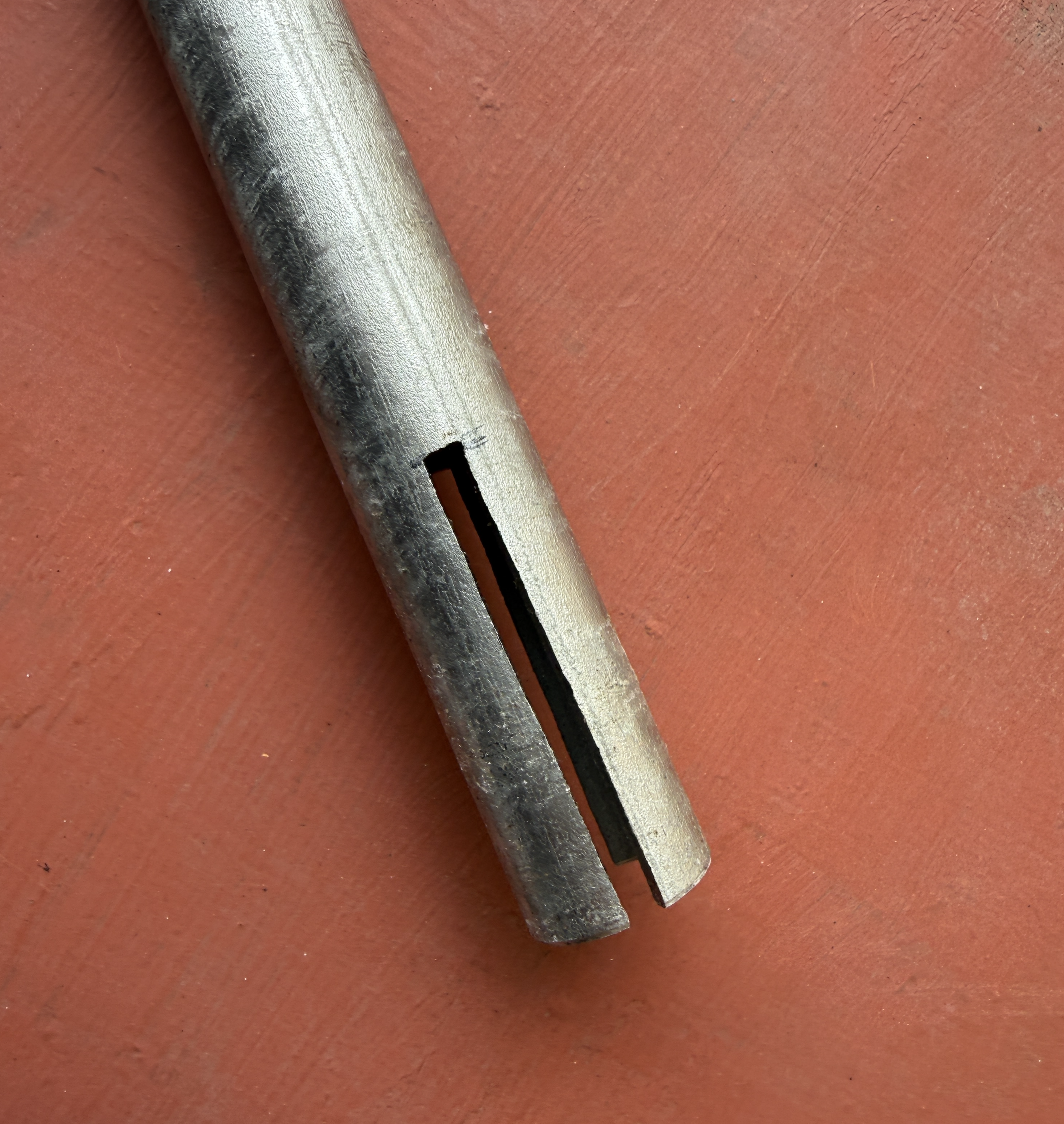
計測したところ、5mm幅で 54mmの高さのスリットでした
Upon measurement, the slits were 5 mm wide and 54 mm high.
スリットについて
当社では15Aのランスパイプの先端にこのようなスリットを入れることを推奨しています.底突きした場合にガスの出口がなくなってしまうからですが、スリットの面積を計算したところ500平方mmでした.15Aのパイプの断面積は204平方mmの2.5倍です.炉底によっぽど沈降物がある場合にはこれでも良いですが、何もなければ炉底のアルミ溶湯に届かないことになりそうです.先端が万が一塞がっても同じ面積の出口が横に確保されている状態を作るには、(炉底に厚い沈降物がない場合は)5mm幅でMax 20.4mmの高さのスリット2本で十分ということになります.20Aの断面積は366平方mmですので、Max 36.6mmのスリット2本(366÷5mm幅÷2本)までという計算になります
(結論だけ知りたい方はここから)
整理すると、
ホース内の流速について
10〜15m/sで調整されていれば5mのホース内にフラックスが停滞して詰まることは起きにくいはずです.ここに溜まって詰まる場合は、流速(ニードルバルブ前後の圧力差)が足りないと考えられるので圧力調整器の二次側圧力を上げてください.
ランスパイプ内の流速について
15Aでも20Aでもパイプ内には微風(2〜1m/s)程度の流速しかないため微粉末部分はこの風に乗りますが、顆粒成分は飛びません.顆粒成分はパイプを立てていれば、自重とガスの重さと1〜2m/sの流速で落ちてきます.大きい保持炉の炉奥を狙う場合にはランスパイプの角度が水平側に近づきますので、流速(圧力差)も流量も上げてください.
今回の内容については諸説あり、神戸オフィスの見解ですのでご質問や技術アドバイスのご依頼(できましたら保持炉洗浄のご依頼も)神戸オフィス宛までお願いします
(English)
Regarding lance pipe slits:
At KANAE, we recommend adding slits like the ones shown here to the tip of our 15A lance pipes. This is to ensure an exit for the gas in the event the pipe hits the furnace bottom. However, upon calculating the area of these slits, I found they totaled 500 $mm^2$—nearly 2.5 times the 204 $mm^2$ cross-sectional area of a 15A pipe. While this is acceptable if there is significant sediment at the furnace bottom, under normal conditions, the gas might escape before even reaching the molten aluminum at the very tip. To ensure that an equivalent exit area is maintained on the sides even if the tip is blocked (assuming no thick sediment), two slits with a width of 5mm and a maximum height of 20.4mm are sufficient. For a 20A pipe, which has a cross-sectional area of 366 $mm^2$, the calculation suggests two slits with a maximum height of 36.6mm (366 ÷ 5mm width ÷ 2 slits) are enough.
(Summary: Read from here if you just want the conclusion)
To summarize the key points:
Hose Flow Velocity
If the flow velocity is adjusted between 10–15 m/s, flux is unlikely to stagnate and clog the hose. If clogging does occur here, it is likely that the flow velocity (the pressure difference across the needle valve) is insufficient. In such cases, please increase the secondary-side pressure of the regulator.
Lance Pipe Flow Velocity
Whether using 15A or 20A pipes, the velocity inside the pipe is only about the strength of a light breeze (1–2 m/s). While fine powders can ride this air, granular components rely on gravity and will only descend properly if the pipe is held vertically. If you are aiming for the back of the furnace and the lance pipe angle approaches a horizontal position, you must increase both the flow velocity (pressure difference) and the flow rate.
These insights represent the technical perspective of our Kobe Office. For questions, technical advice, or requests for holding furnace cleaning services, please contact the Kobe Office directly.